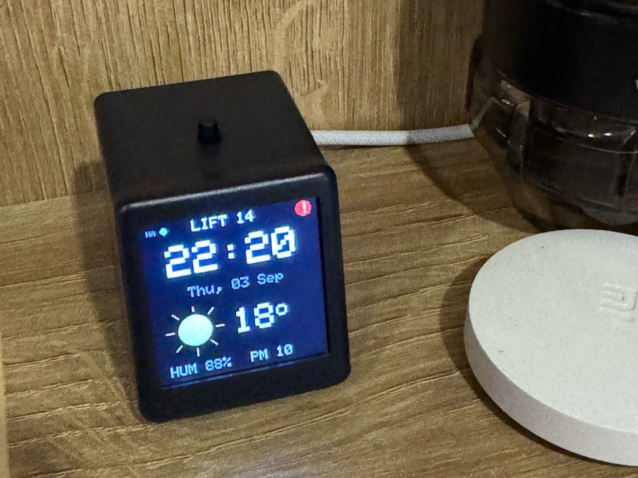
A DIY apartment elevator call and tracking system built with ESP8266, Home Assistant, MQTT, and computer vision — without modifying the elevator controller.
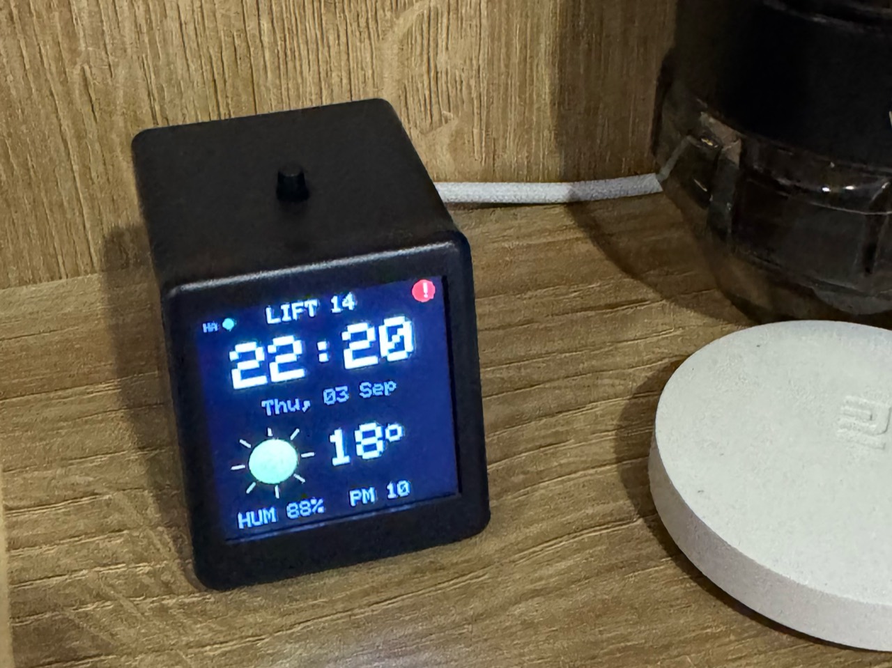
Call14 began with a small question: why wait in the hallway for the elevator when it could be called while you are still getting ready to leave?
I live with my family on the 14th floor in Kyiv. Waiting several minutes for an elevator is normally just an inconvenience. During air-raid alerts, however, getting the children ready and reaching shelter quickly can make those minutes feel much more important.
I am an entrepreneur, not a professional programmer or electronics engineer. This is a hobby project, and it was my first time building a system like this. I learned each layer — UART flashing, ESP8266 firmware, Home Assistant, MQTT, and computer vision — when the project required it.
What began as a round Xiaomi smart button named “Lift Button” at home grew into a complete system:
- an ESP8266 relay electrically reproduces pressing the existing hall-call button;
- a local computer-vision service reads the floor indicator visible through an authorized cabin camera;
- Home Assistant connects the call control, elevator telemetry, weather, air-raid alerts, and backup-power data;
- a modified inexpensive ESP8266 clock near the apartment door provides a physical call button and an always-on status display.
I did not want this convenience to belong to one apartment only, so every neighbour on our floor can also call the elevator through DomoBot, the Telegram bot we built for our building. DomoBot deserves a separate story of its own; here it is simply another interface to the same Home Assistant call script.
See it work
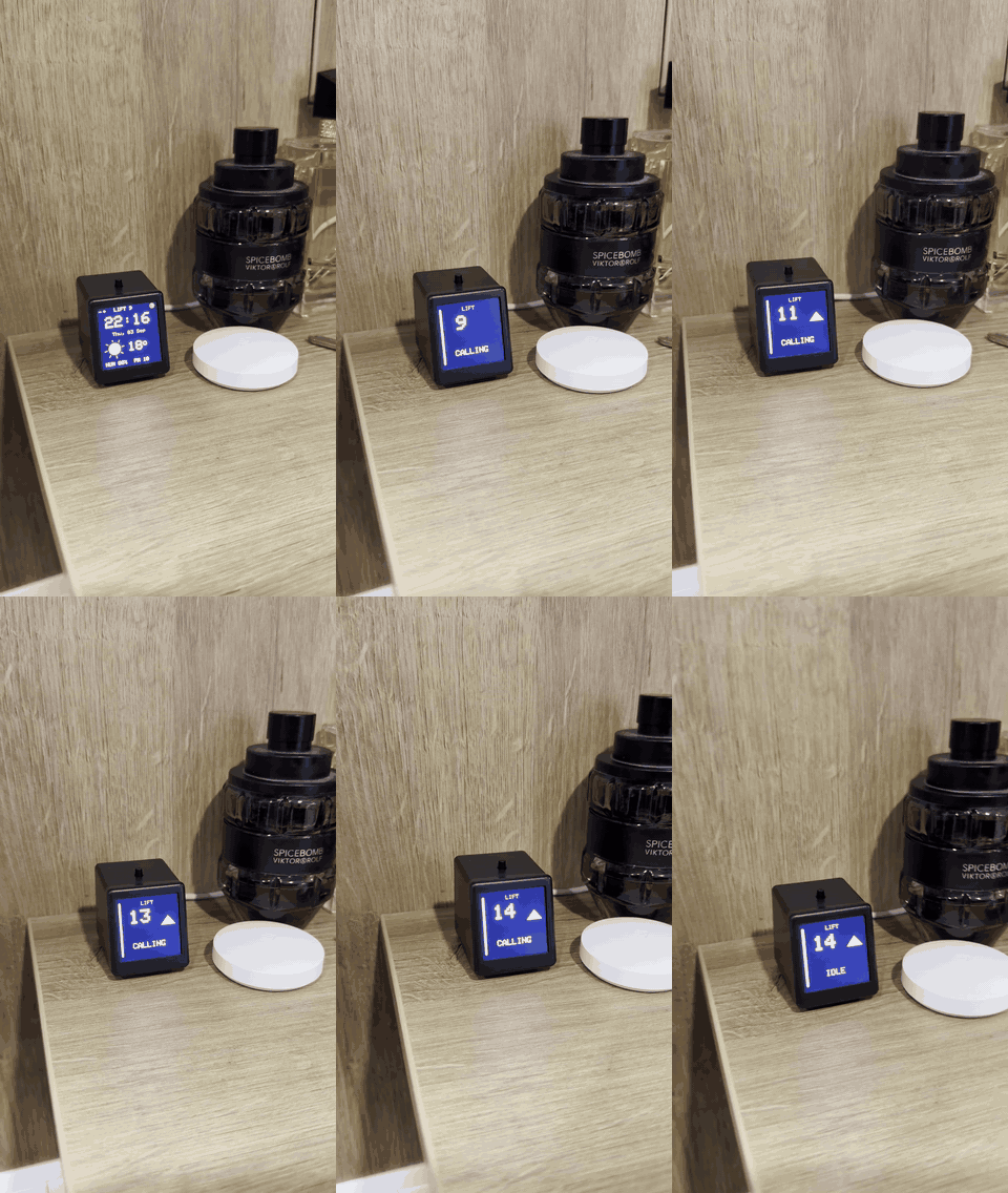
Press the button, watch the interface switch from the home screen to CALLING,
follow the recognized floor and direction, and see it settle on IDLE at floor
14. The animation is a 3×-speed silent preview; click it for the full real-time
MP4. Recognition and display updates remain on the local network.
What it cost
The surprising part is that hardware was not the expensive part. My total new spend was no more than about USD 20; most of the real cost was thought, experimentation, repeated soldering, and roughly six months of spare-time iteration.
| Part | What I used | Approximate cost |
|---|---|---|
| Hall-call relay and cable | XY-WF36V/ESP8285 relay plus roughly 10 m of low-voltage cable | under $10 total |
| Indoor button | An existing Xiaomi smart button | $0 for me |
| Optional new button | Any compatible battery Wi-Fi/Zigbee button | about $10 |
| Call14 clock | JUZIPi SD_PRO-style ESP8266 clock | 224–230 UAH, about $5–6 |
| Added tactile switch | A spare normally-open switch | a few cents |
| Home Assistant server | An old Mac already running at home | $0 incremental |
| Recognizer camera | Existing authorized cabin-security camera | $0 incremental |
| Software | ESPHome, Home Assistant, MQTT and the local recognizer | $0 |
A phone or Home Assistant dashboard can call the elevator without buying the indoor button. Likewise, an old computer or laptop is sufficient for the local services; a new server is not a project requirement.
Example listings used or considered during the build:
- Wi-Fi relay similar to the installed module
- Battery smart button that does not require a separate hub
- ESP8266 clock used as the display enclosure and hardware base
Listings and prices change. Select hardware by electrical requirements and verified pinout, not by enclosure appearance alone.
Choose how far you want to take it
Call14 can be reproduced in independent stages:
- Remote call only. Use a compatible Wi-Fi relay's original application and call from a phone. No Home Assistant, display or camera is required.
- Local smart-home call. Flash the relay with the provided ESPHome configuration, then call it from Home Assistant, a phone or a wireless button.
- Floor tracking. Add an authorized camera and adapt the hybrid v6 recognizer. The included Codex setup prompt guides calibration for another indicator instead of reusing camera-specific coordinates blindly.
- Complete Call14 terminal. Modify the supported clock, flash the display firmware, and connect the Home Assistant MQTT bridge.
Each stage remains useful on its own. Start with the smallest version that fits your building rules, authorization, hardware and experience.
How the complete system works
Call14 has two deliberately separate paths. The control path can only reproduce a hall-button press. The observation path can only watch the existing indicator. They meet in Home Assistant, but neither depends on direct access to the elevator controller.
flowchart LR
    subgraph Home[Inside the apartment]
        Clock[Call14 display\nESP8266 + button]
        Xiaomi[Xiaomi smart button]
        HA[Home Assistant]
        MQTT[Local MQTT broker]
    end

    subgraph Landing[14th-floor landing]
        Relay[ESP relay\ndry contact]
        Hall[Original hall-call button]
    end

    subgraph Cabin[Elevator cabin — read only]
        Indicator[Original floor indicator]
        Camera[Authorized camera]
    end

    subgraph Server[Local server]
        V6[Aligned hybrid recognizer v6]
    end

    Clock -->|PRESS| MQTT
    Xiaomi --> HA
    MQTT <--> HA
    HA -->|short pulse| Relay
    Relay -. parallel contact .-> Hall

    Indicator --> Camera
    Camera -->|local video stream| V6
    V6 -->|floor + direction + state| MQTT
    HA -->|display topics| MQTT
    MQTT --> Clock
What happens after one press
- I press the small button on top of the Call14 display while getting ready to leave.
- The ESP8266 publishes a local
PRESSevent over MQTT and immediately opens the elevator screen, so the interaction feels instant. - Home Assistant runs the same call script used by the Xiaomi button and phone dashboard.
- The landing relay closes its isolated contact for a short pulse. Electrically, the elevator sees the same event as a finger pressing the original button.
- The camera recognizer independently observes the cabin indicator and sends the confirmed floor and direction back through MQTT.
- The display follows the elevator until it arrives. By the time I lock the apartment and reach the landing, the doors can already be opening ��� the small everyday moment that made the whole project feel worthwhile.
The normal hall-call button continues to work even if Wi-Fi, Home Assistant, the camera, or the display is offline. Recognition is also not part of the call circuit: losing the video feed only removes telemetry.
The Home Assistant view
The dashboard combines the live cabin view with a custom elevator card. Its seven-segment styling mirrors the physical indicator and shows the confirmed floor, direction and motion state. The button at the bottom calls the elevator to the 14th floor through the same script used by the physical interfaces.
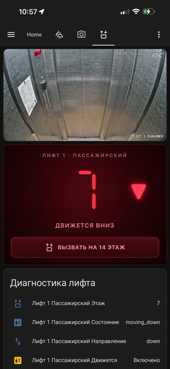
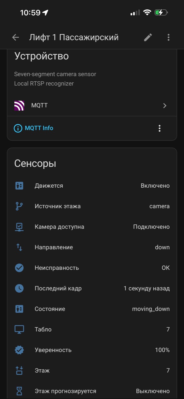
MQTT Discovery creates a dedicated elevator device instead of a loose collection
of values. Alongside the main floor and direction it exposes camera availability,
recognizer confidence, last-frame time, fault state and whether a value is
camera-confirmed or estimated. In production v6, dead-reckoned floor prediction
is disabled; the screenshot therefore reports camera as the source and 100%
confidence for this observation.
Part 1: calling the elevator from home
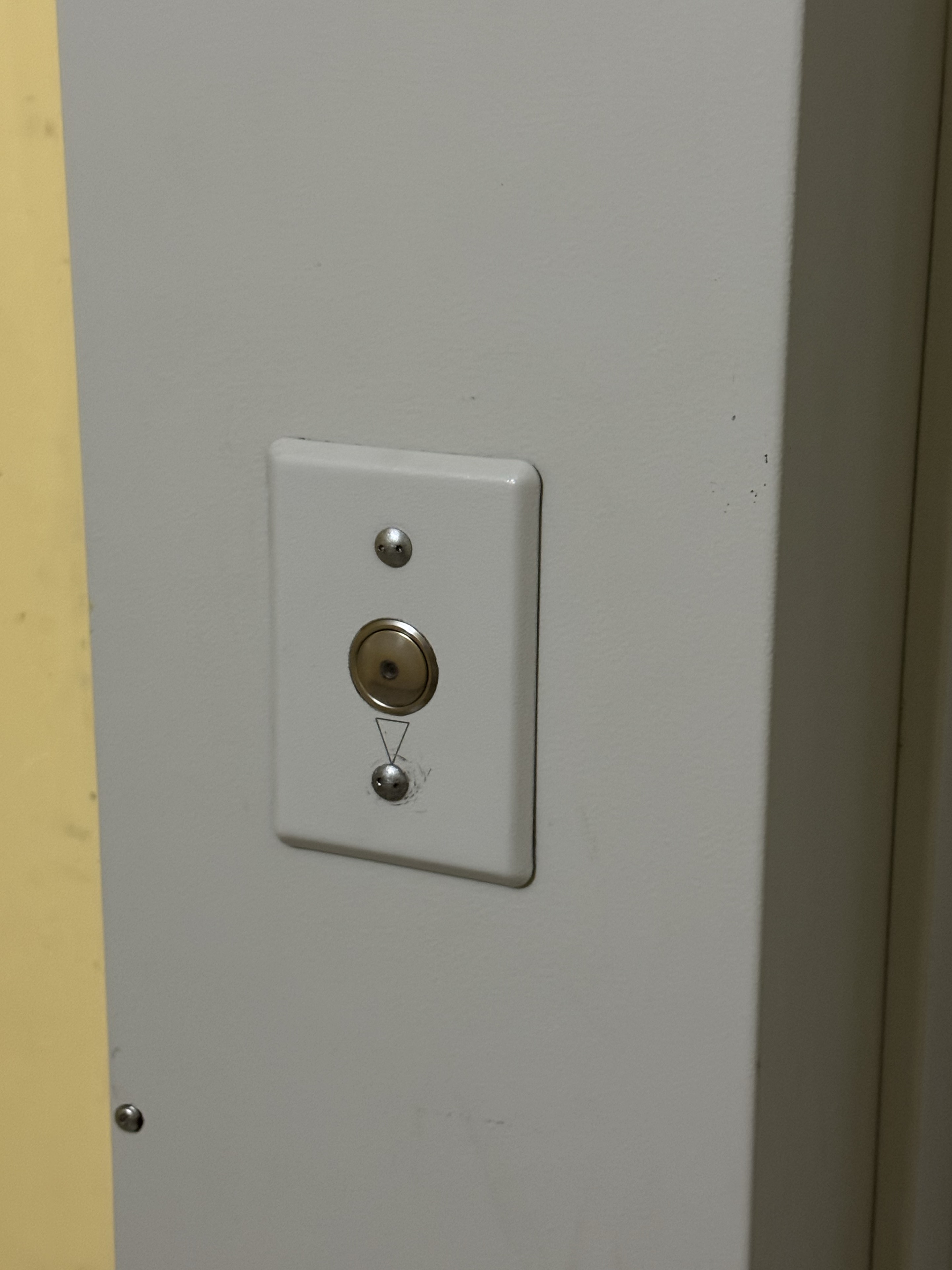
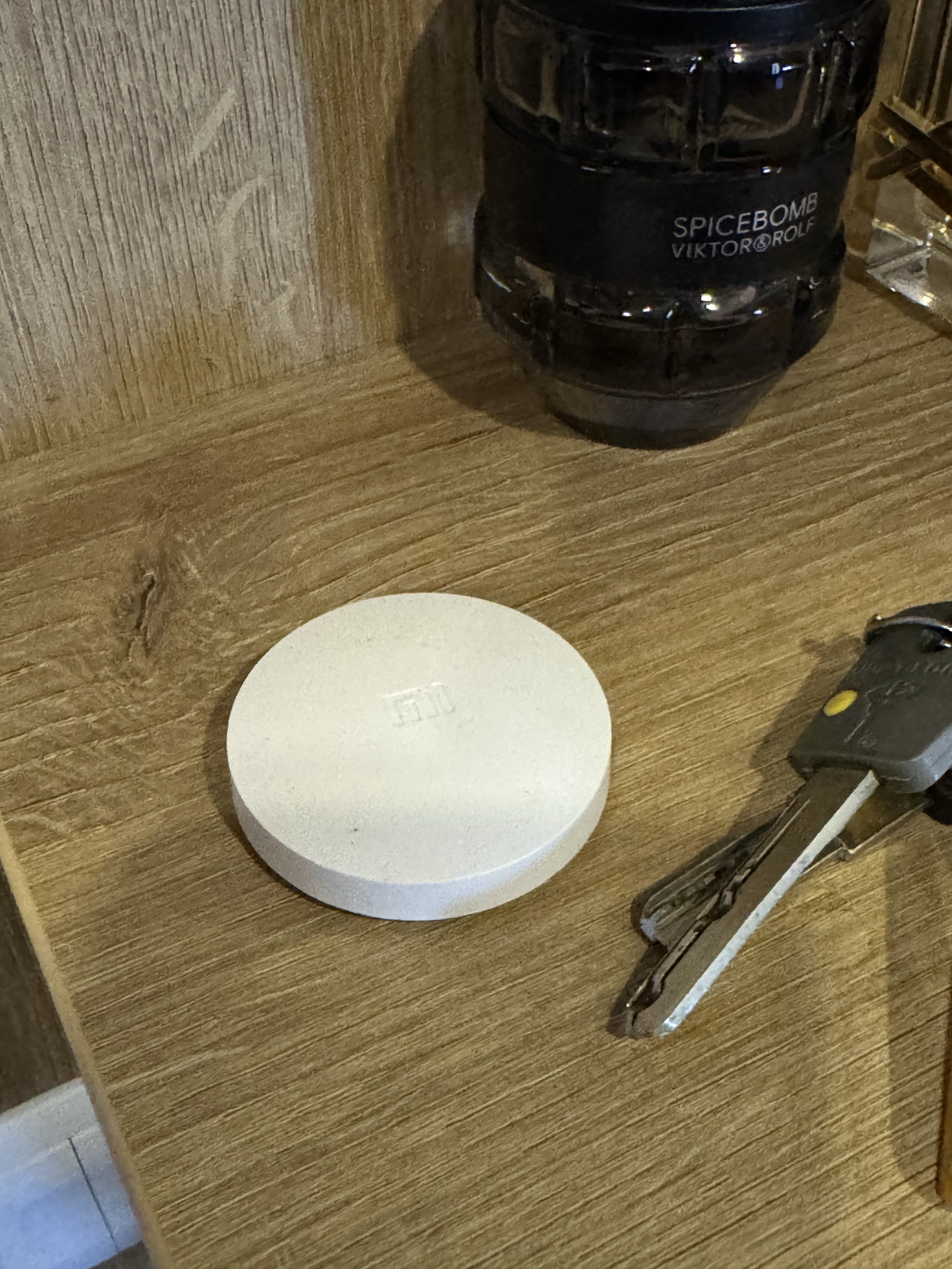
The first version solved only one problem: calling the elevator without first walking into the hallway. A round Xiaomi smart button that I already used with my smart home became the interface. In Home Assistant — and soon in our family vocabulary — it was simply called Lift Button.
Later, the call action was made available through DomoBot to every resident on our floor. The hardware remained exactly the same: the bot only asks Home Assistant to run the same short, local call-button pulse. The story of the building-wide Telegram bot will be a separate project.
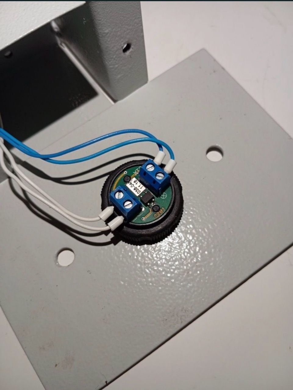
Behind the existing hall-call button, I identified the two contacts closed by a normal press and connected an isolated relay contact in parallel. The original button continues to work normally; Call14 merely reproduces the same momentary contact closure.
The first hardware assumption that failed
I chose an inexpensive XY-WF36V Wi-Fi relay module because it accepts a wide
DC supply range. Many elevator call-button circuits use approximately 12–24 V
DC, so I hoped the same local supply could power the module while its dry relay
contact reproduced the button press.
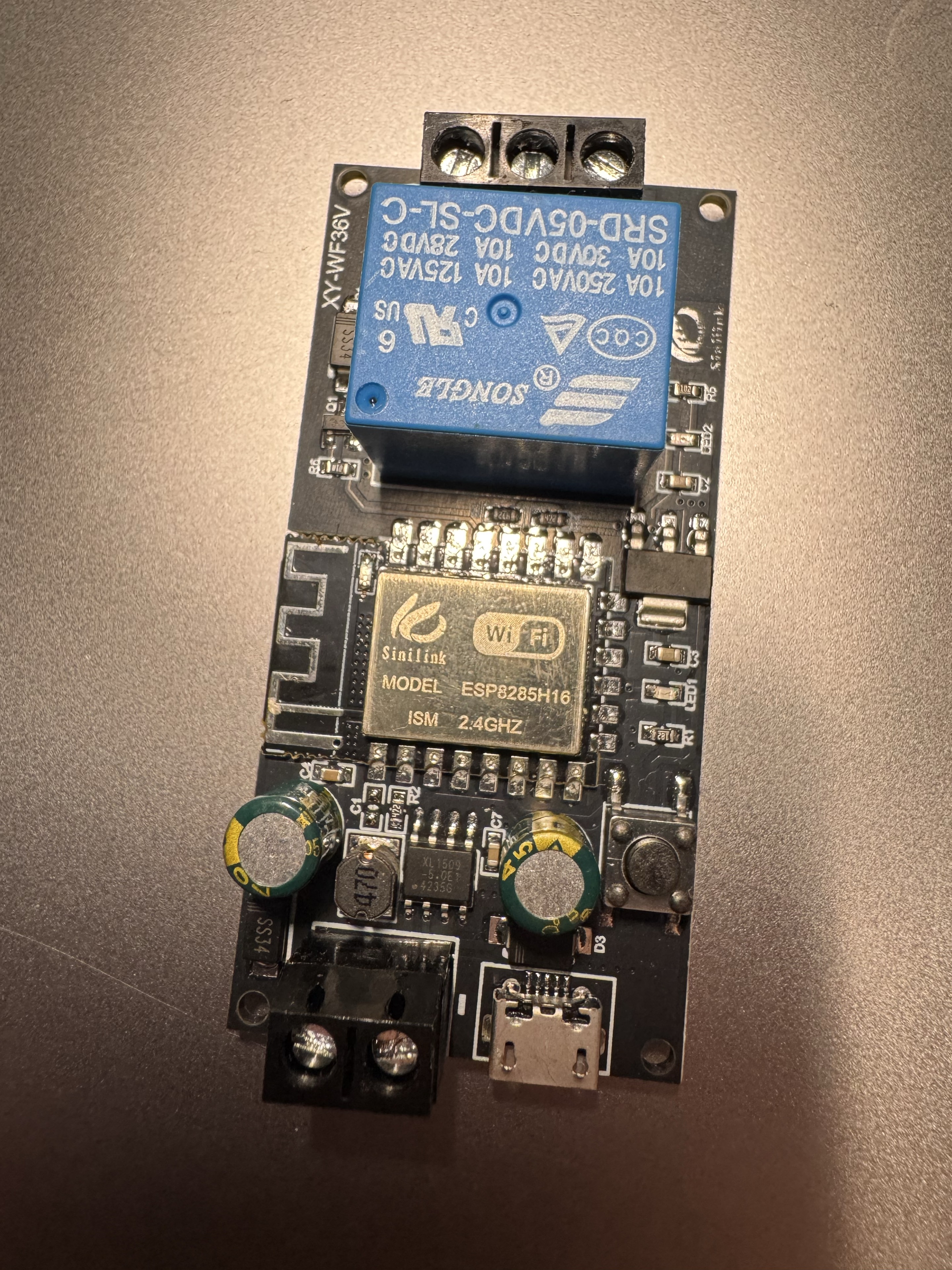
My elevator had a surprise waiting: the available button voltage was about 24 V AC, not DC. The selected module could not be powered from it directly. I ultimately ran roughly 10 metres of low-voltage cable from an existing access control power supply on the floor.
This became the first reusable lesson of the project: measure the available voltage and confirm both its level and whether it is AC or DC before selecting the relay and power architecture.
Replacing the vendor firmware
The module already had its own mobile application, and someone interested only in remote calling could keep that simpler setup. My goal was deeper integration with Home Assistant and local automations, so I connected to the module's UART pads and replaced the original firmware.
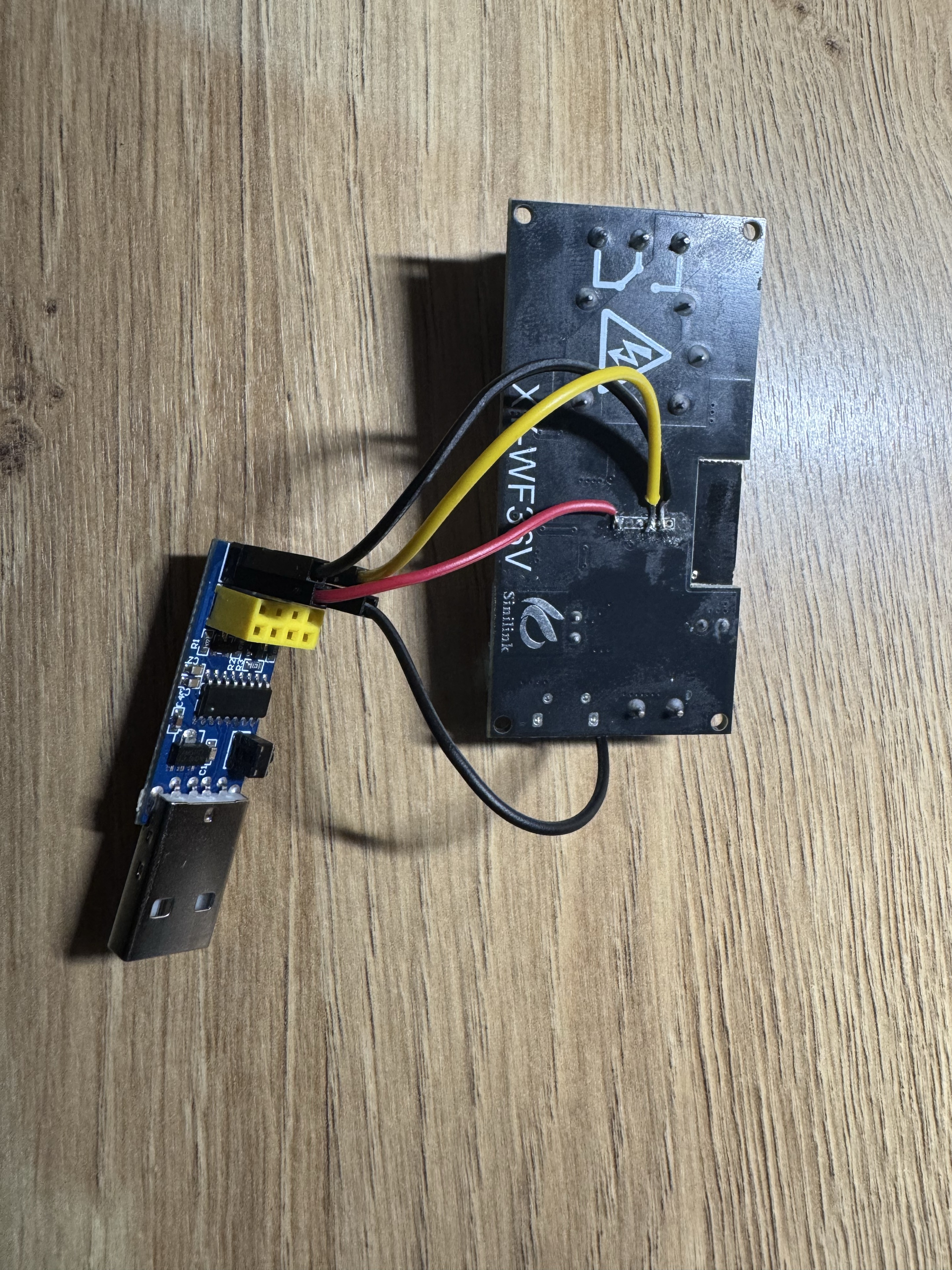
To enter the ESP8266 serial bootloader, GPIO0 must be held to ground during
reset or power-up. After the initial wired flash, OTA updates allowed later
changes over Wi-Fi.
The complete verified pin tables and connection notes are in
docs/WIRING.md.
The public release will include a generic configuration with credentials, addresses, and installation-specific values removed.
Several ways to build only this part
The full Call14 system uses Home Assistant, but the basic remote-call function does not require the display or computer vision. It could be implemented with:
- the relay manufacturer's original application;
- a phone control exposed by a smart-home platform;
- an inexpensive Zigbee/Wi-Fi button similar to the original Xiaomi button;
- Home Assistant and a local automation, as used in this project.
Automatic calling based on air-raid alerts was also considered. Because alerts are frequent and an automatic call could summon the elevator when nobody is actually leaving, the production system deliberately keeps elevator calling a manual action.
Part 2: turning a $5 clock into Call14
Once Home Assistant knew the elevator's floor and direction, a new usability problem appeared: checking a phone every time before leaving was too slow and too distracting. The information needed a permanent place near the front door.
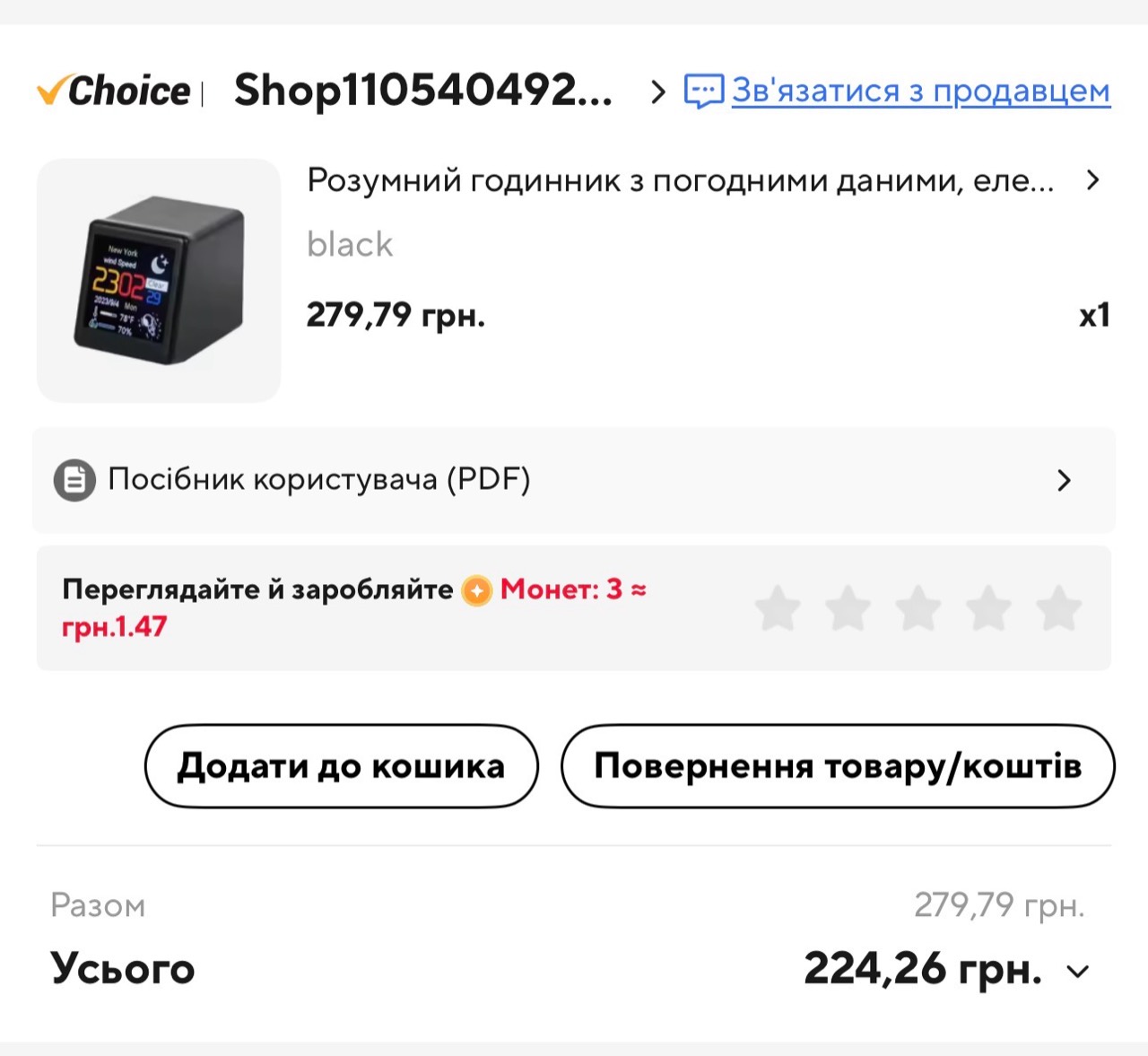
I found a tiny JUZIPi SD_PRO-style weather clock on AliExpress and paid 224.26 UAH including delivery during a promotion — approximately USD 5 at the time.
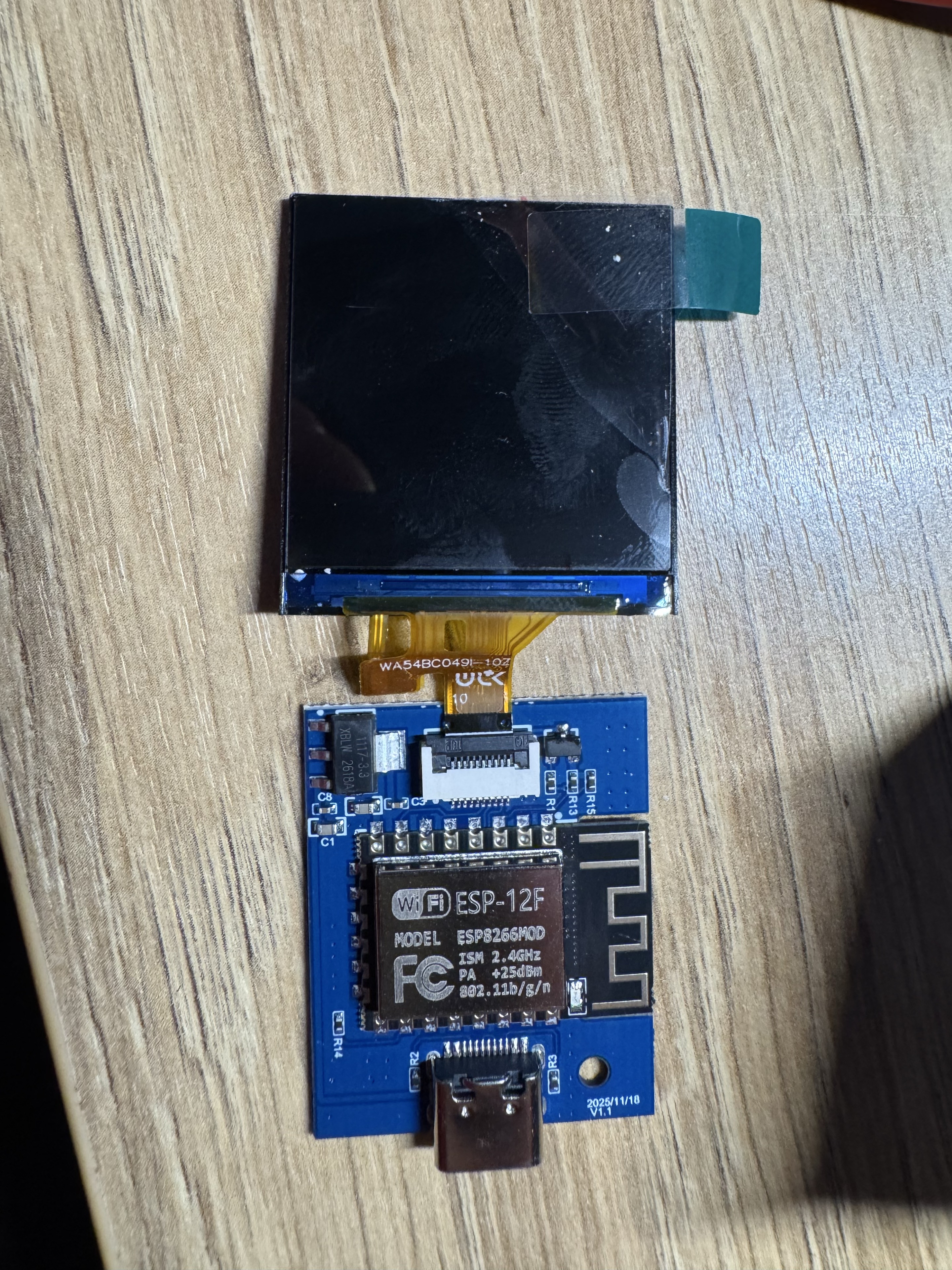
The enclosure contained an ESP8266 ESP-12F module and a 240×240 color display. That made it powerful enough for Wi-Fi, MQTT, a lightweight custom interface, and OTA updates, but limited enough that memory use and screen redraws had to be treated carefully.
A custom firmware, with a recovery path
The original clock already supported browser firmware updates, which provided a convenient route for the first custom build. Losing that update path would mean reopening the case and flashing over UART, so recoverability became a first-class requirement rather than an afterthought.
That caution turned out to be justified. During development I repeatedly had to open the enclosure, solder to the board, connect my ESP programmer, enter a special recovery/boot mode, and restore a working firmware before continuing.
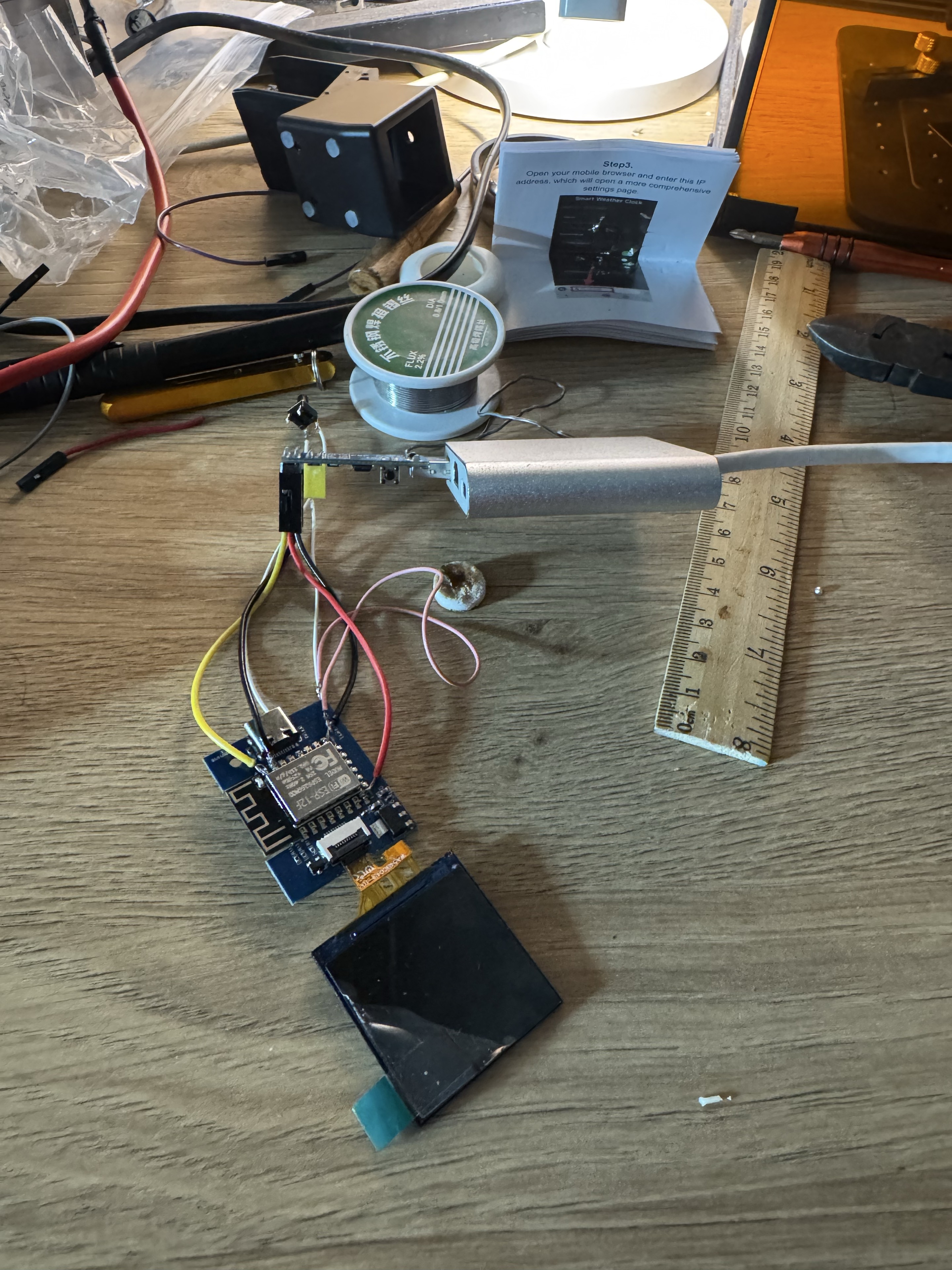
The finished firmware keeps both web-based firmware upload and Arduino OTA, along with a fallback recovery access point. It also includes a display-safe startup mode: holding the added button during power-up leaves the display disabled while networking and the update interface remain available.
Some newer factory releases already expose browser OTA, which can make the first custom flash deceptively easy. Verify the display controller and pin mapping before using it. An OTA upload may succeed even when the new firmware cannot drive the screen. That exact mistake left this clock with a black display and forced another teardown, direct ESP8266 UART soldering, and bootloader recovery.
Adding the missing physical control
The rear of the clock PCB exposes three pads marked G V O. A continuity test
confirmed that O connects to GPIO4, a suitable input that is not one of
the ESP8266's boot-strap pins. The firmware configures it with the internal
pull-up resistor, and a normally-open button shorts O to G when pressed.
I used a small tactile switch that was already in my electronics parts box, drilled one hole in the top of the enclosure, and fixed the switch in place.
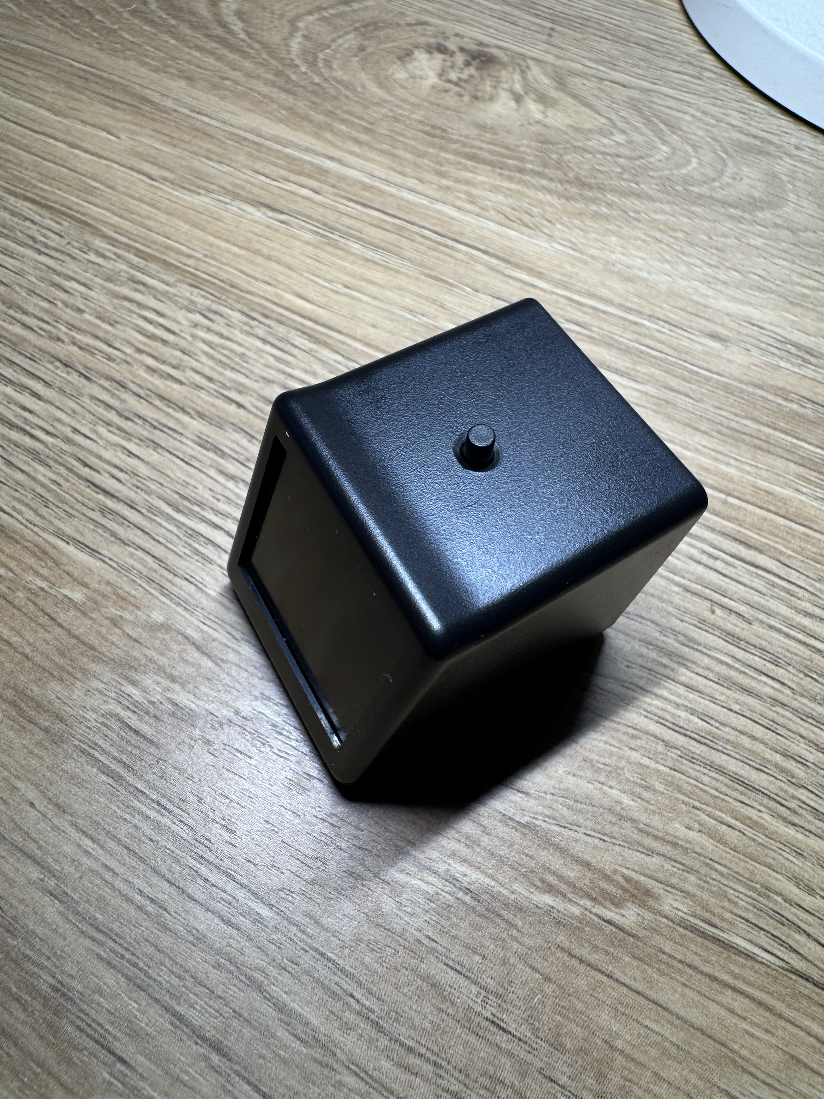
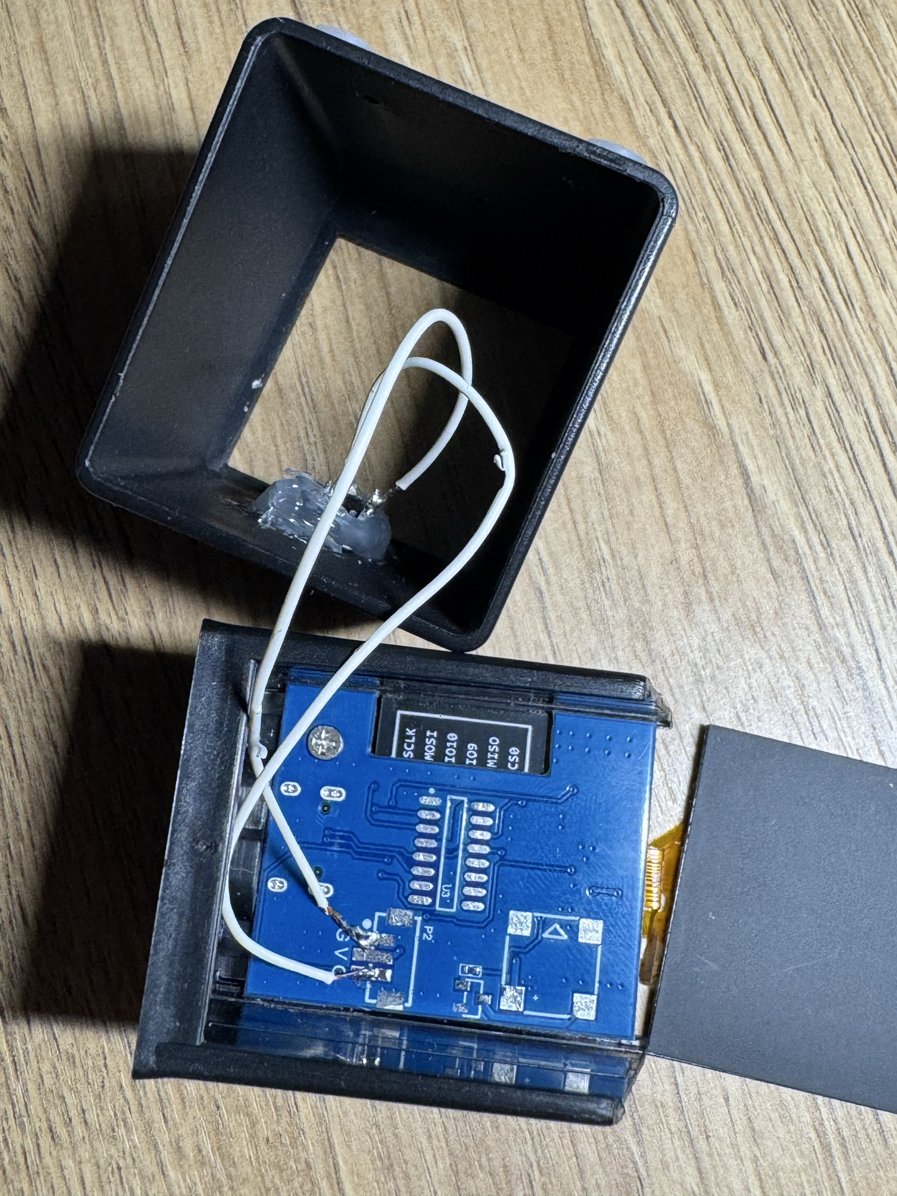
A capacitive touch sensor could be used in a future build to avoid drilling the case. I kept the mechanical button because it provides clear tactile feedback and can be pressed without looking at the device.
The button is context-aware: a normal press calls the elevator when the regular home screen is visible; while the elevator view is already open, it changes the display page instead. A long press cycles screen brightness.
From generic clock to home status terminal
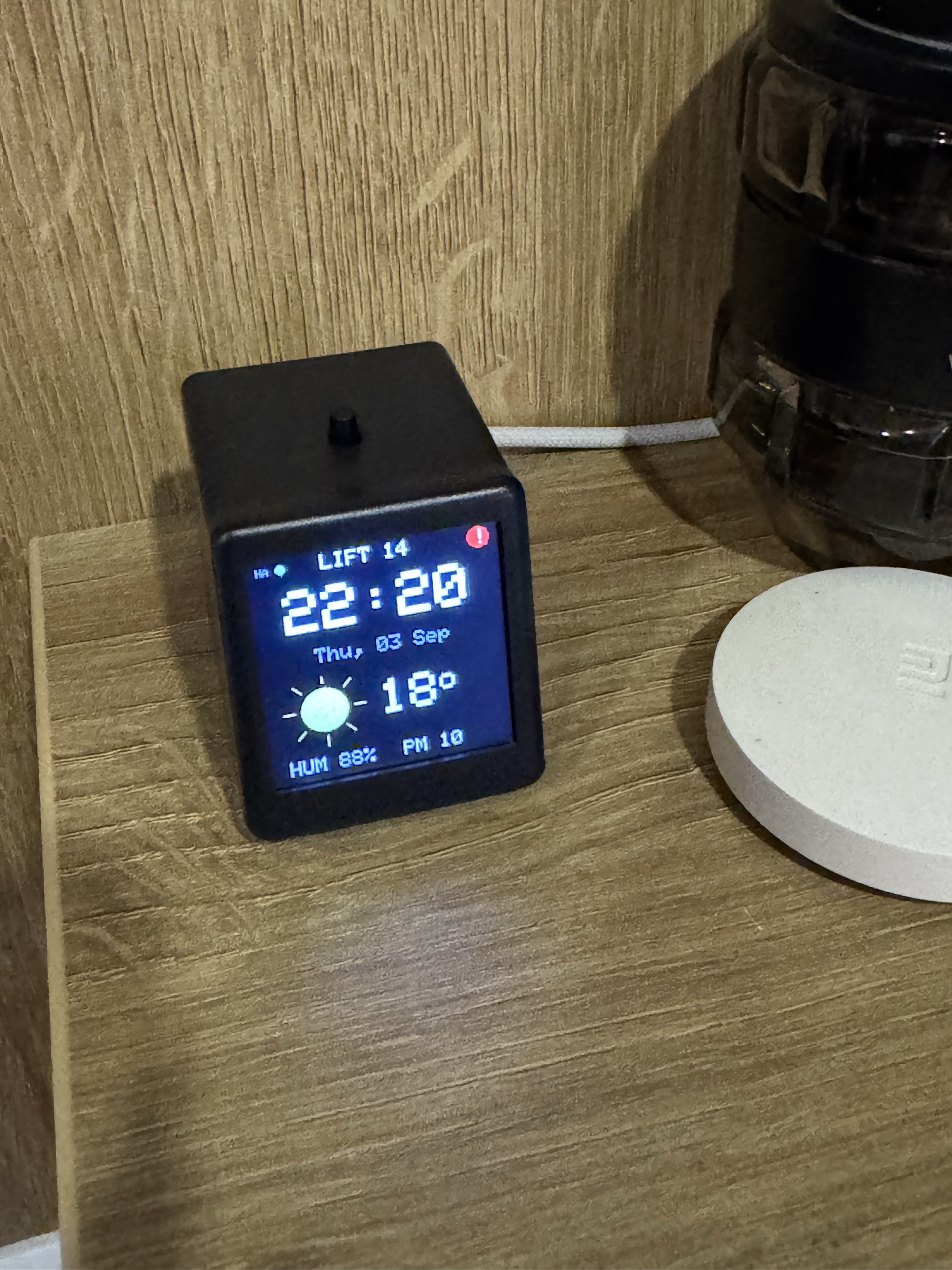
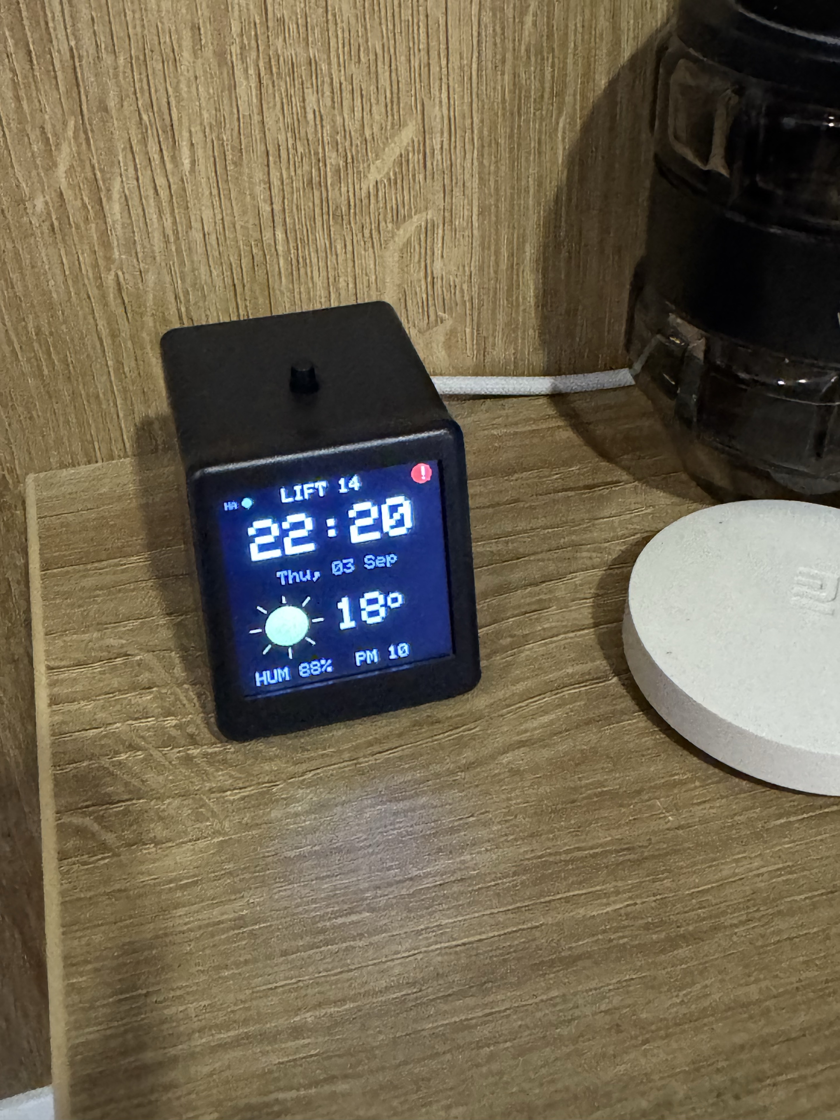
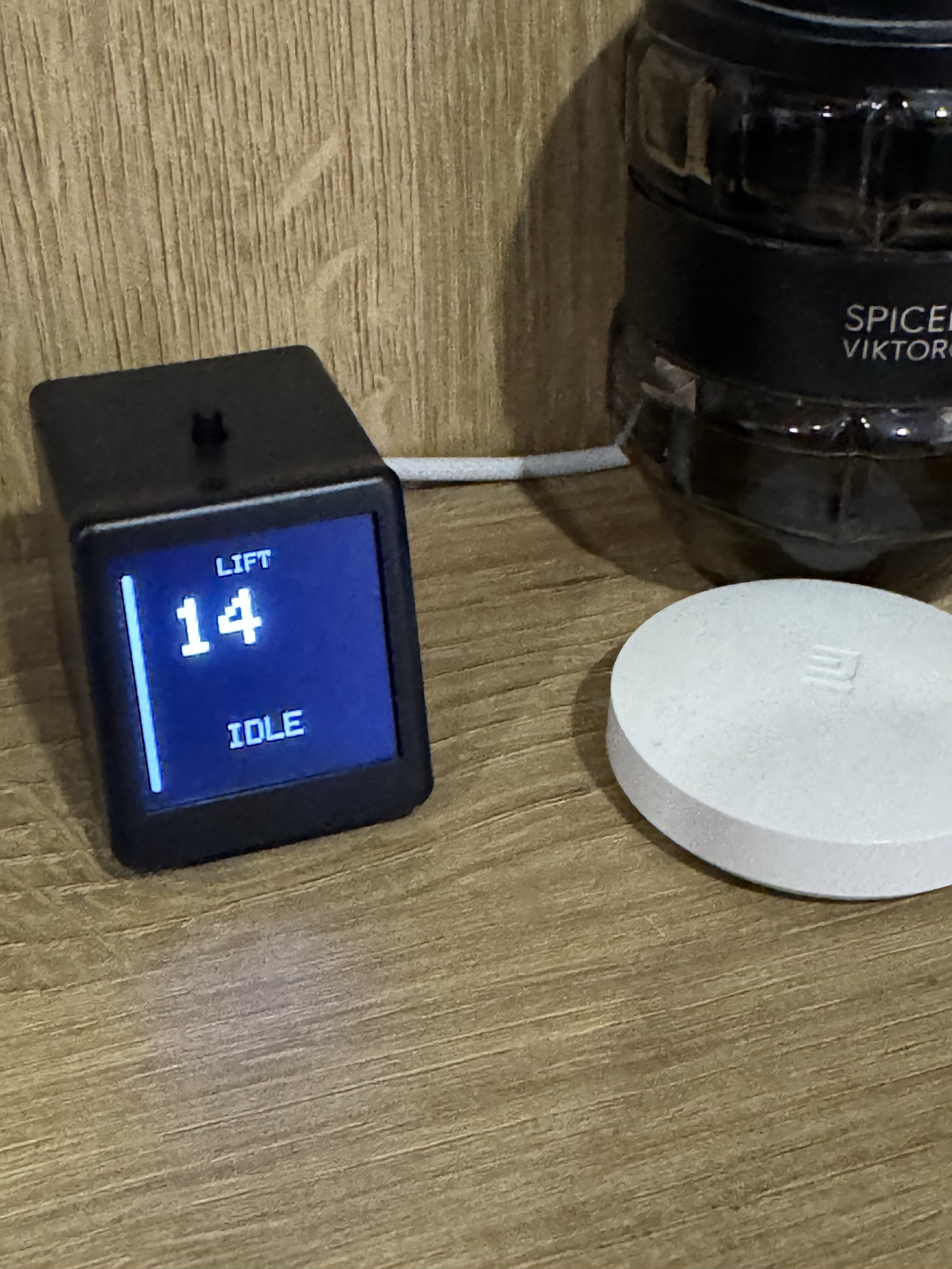
The clock still shows time, date, weather, humidity, and air quality, but its top line now continuously reports the elevator floor. When a call is made, the interface switches to a dedicated elevator view with a large floor number, direction, and state.
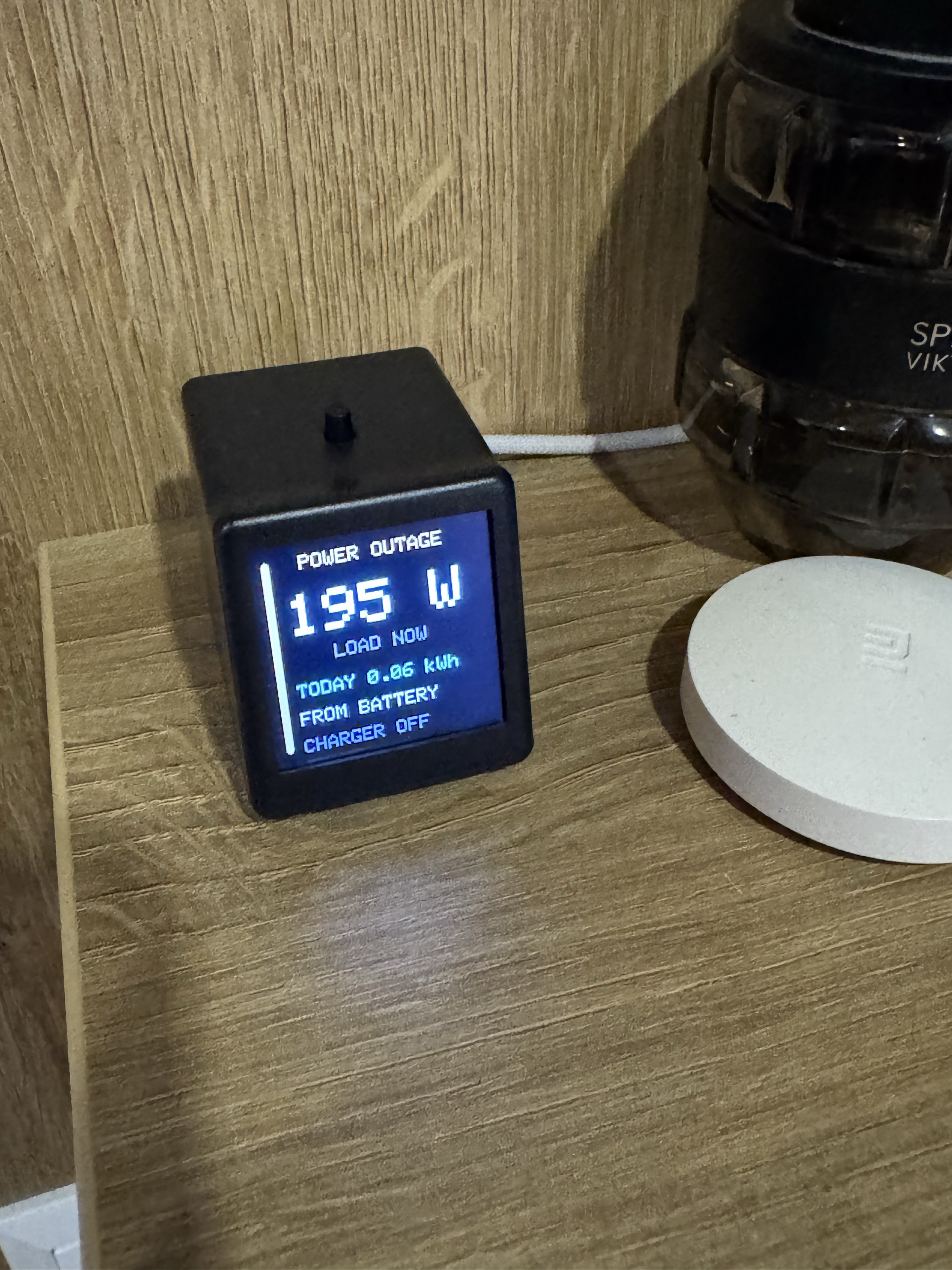
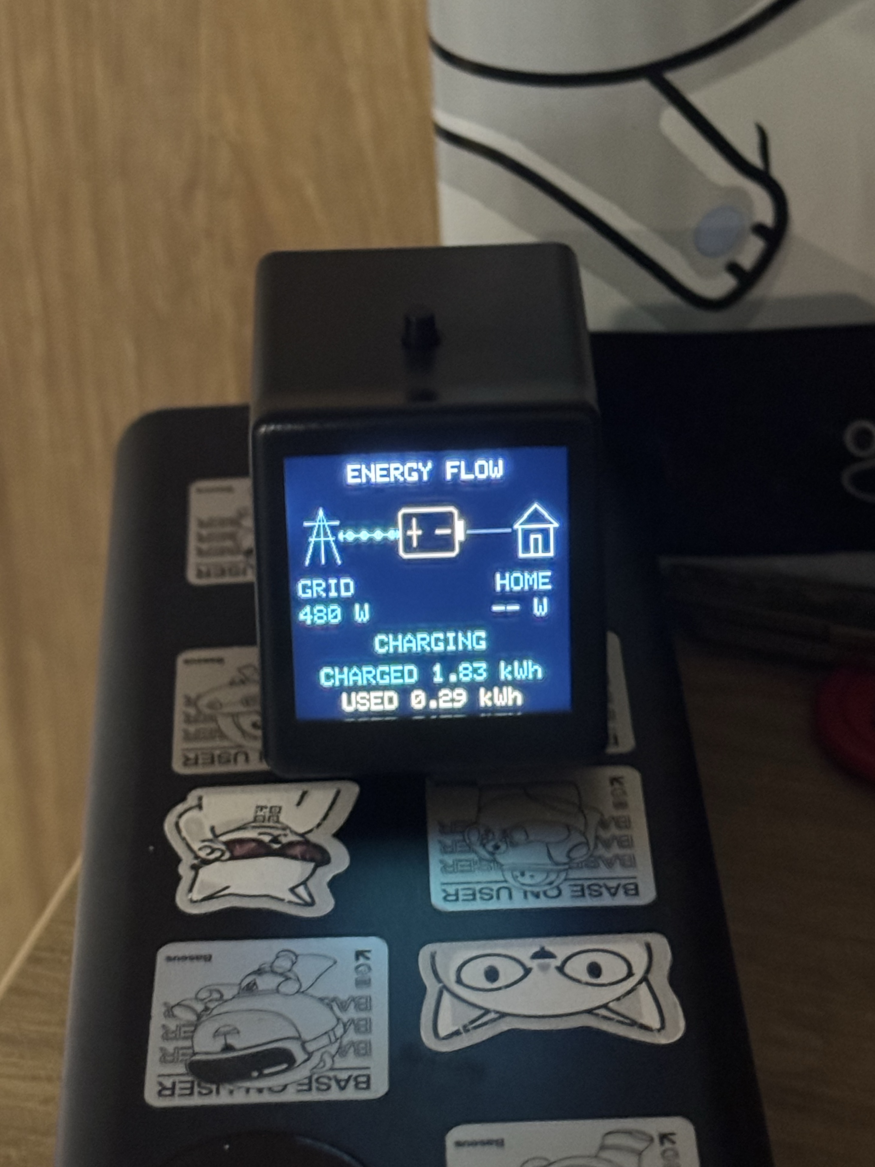
The same display can surface air-raid status and practical household power information from Home Assistant, including grid availability, inverter state, and battery charge. The project had stopped being only an elevator button; it had become a small always-on home terminal.
| Daily home view | Dedicated elevator view |
|---|---|
 |
 |
| Power outage view | Energy-flow view |
|---|---|
 |
 |
Power-outage response demo
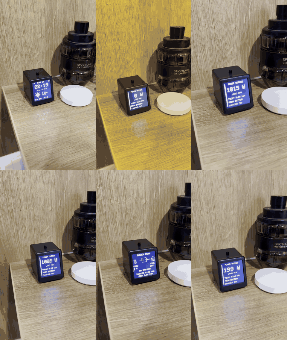
When grid power disappears, Call14 leaves the ordinary clock view and surfaces the information that matters now: current household load, energy used during the outage, whether the battery is supplying the home, and charger state. It can then show the complete energy path between grid, battery and household load. The silent animation is accelerated; click it for the edited real-time MP4.
Firmware interface gallery
The firmware contains several purpose-built views rather than one overloaded dashboard. The final gallery will document each of these real screens:
| View | Purpose |
|---|---|
| Home | Time, date, animated weather, temperature, humidity, PM2.5, HA status, and current elevator floor |
| Elevator | Large floor number, direction arrow, and IDLE, CALLING, MOVING, or ARRIVED state |
| Energy flow | Visual path between grid, charger/battery, and home load |
| Inverter | Battery charge, household load, estimated runtime, and grid state |
| Charger | Charger state, charging power, accumulated energy, and battery metrics |
| Air raid | Full-screen alarm warning followed by a persistent red indicator |
| All clear | Short full-screen confirmation when an alert ends |
| Motion | Temporary local motion notification from Home Assistant |
| Boot/diagnostic | Startup, network state, and recovery information |
These views are drawn directly with lightweight TFT primitives. Animated weather icons and partial redraws keep the interface alive without the memory cost of GIF playback or a heavyweight GUI framework on the ESP8266.
Clean 240×240 design illustrations reconstructed from the firmware will accompany these real device photographs in the final documentation.
Part 3: teaching a camera to read the elevator
The elevator controller offered no supported integration API, and the elevator company was understandably not enthusiastic when a self-taught entrepreneur asked to connect a homemade gadget to its control board. That refusal led to a much safer architecture: observe the indicator, never control the elevator.
An already authorized cabin camera sees the original red floor indicator. A local service crops only that small region, determines the floor and illuminated direction arrow, and publishes the result to Home Assistant over MQTT. No cabin video or cloud vision service is required for recognition.
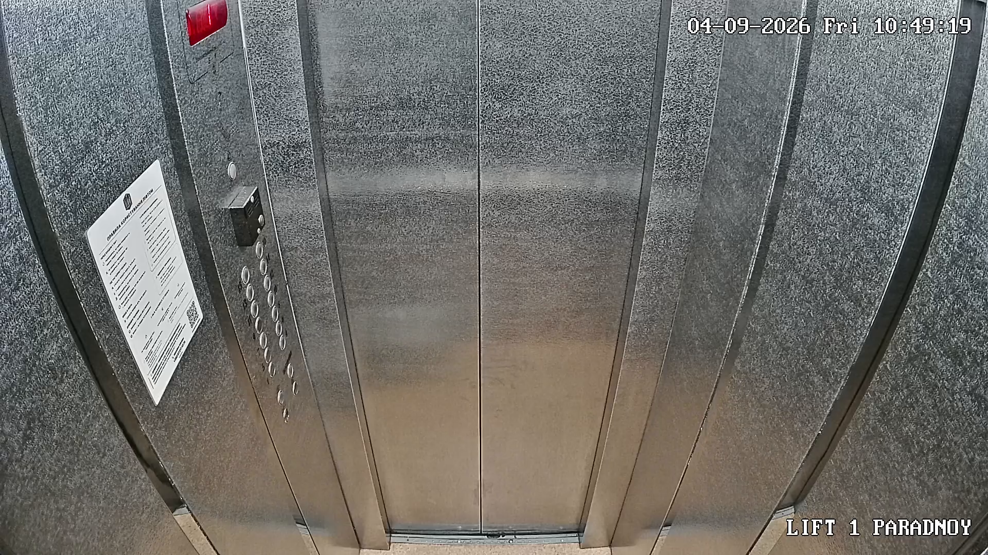
The camera was installed for ordinary building security; Call14 only reuses its local stream as a read-only sensor. The tiny red indicator in the upper-left corner of this frame is the complete visual input to the recognizer.
Why ordinary OCR was not enough
The display looks easy to a human, but it is unusually unfriendly to a camera:
- the glossy red cover reflects passengers, clothing, phones, and even a courier's shiny helmet;
- opening the doors replaces dim cabin light with brighter or darker landing light, depending on floor, weather, and time of day;
- people entering the cabin change both exposure and reflections;
- the digits and arrows are multiplexed LEDs, so one video frame may capture only part of a symbol;
- perspective turns a clean seven-segment digit into a small, slanted shape.
- tiny camera or decoder shifts move narrow LED strokes away from fixed masks.
Early OCR and whole-image matching sometimes read 14 as 9, expanded 1
into 11, lost an arrow for a frame, or accepted a reflection as a new floor.
These were not rare laboratory curiosities: they appeared only during real
rides, which is why recording and replaying complete journeys became essential.
This was the point where I was running out of patience — and confidence in the whole approach. I had rebuilt and tested several recognizers, yet another passenger or change of light could undo the progress. I was close to abandoning camera recognition and returning to the elevator company to ask for permission to connect an ESP module directly to the controller. Besides being difficult to get approved, that path would also have crossed the clean safety boundary I wanted the project to keep.
The idea that unlocked version 5
Then I reconsidered what the camera actually needed to know. It did not need to understand the complete photograph, the red glass, or anything reflected in it. The decisive idea was to stop asking, “Which digit does this picture resemble?” and instead ask, “Which of the seven physical LED segments are actually on?”
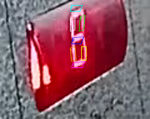
For each segment a through g, the decoder samples a small mask placed well
inside the expected illuminated stroke. It separately samples the tens digit.
Color channels are combined to emphasize the pale LED light through the red
cover, then normalized against the current frame. The resulting seven-bit code
maps directly to digits 0–9.
This point-based approach ignores most of the image. A new reflection can cover half the panel without mattering, provided the small pieces of evidence inside the real segments remain consistent.
A hybrid recognizer, not one clever threshold
Segment decoding is the primary reader, but production v6 surrounds it with several independent safeguards:
- Every crop is first translated back to calibration geometry using stationary
metal beside the display. Low-quality alignment fails closed as
unreadable. - Three consecutive frames are used without blending neighbouring floor digits together. Recognition runs at 4 fps.
- Three independent readers inspect green/blue evidence, red-channel evidence and physical segment geometry.
- A segment result is accepted only when its seven-bit pattern is exact, its confidence clears the calibrated margin, and the floor is physically possible from the last confirmed state.
- Direction-specific image templates provide a fallback when glare makes the segment evidence uncertain. Up, down, and idle images are never casually compared with one another because the illuminated arrow changes the panel.
- A state machine normally permits only the current or next valid floor in the
direction of travel. The building's real floor sequence is encoded as
1, 4, 5, ... 16, including the physical jump between floors 1 and 4. - Arrow detection uses a bright core minus nearby background plus hysteresis. Positive light starts movement immediately; a short dark scan phase does not stop it. Several consecutive misses are required before the state returns to idle.
- A wrong saved position may be corrected only after two physical decoders agree exactly for about three seconds on a well-aligned stationary image.
- An unreadable or reflective frame preserves the last confirmed floor instead of inventing a more visually tempting answer.
In short, image recognition proposes an observation; temporal consistency and the elevator's physical behaviour decide whether that observation is believable.
Live floor recognition
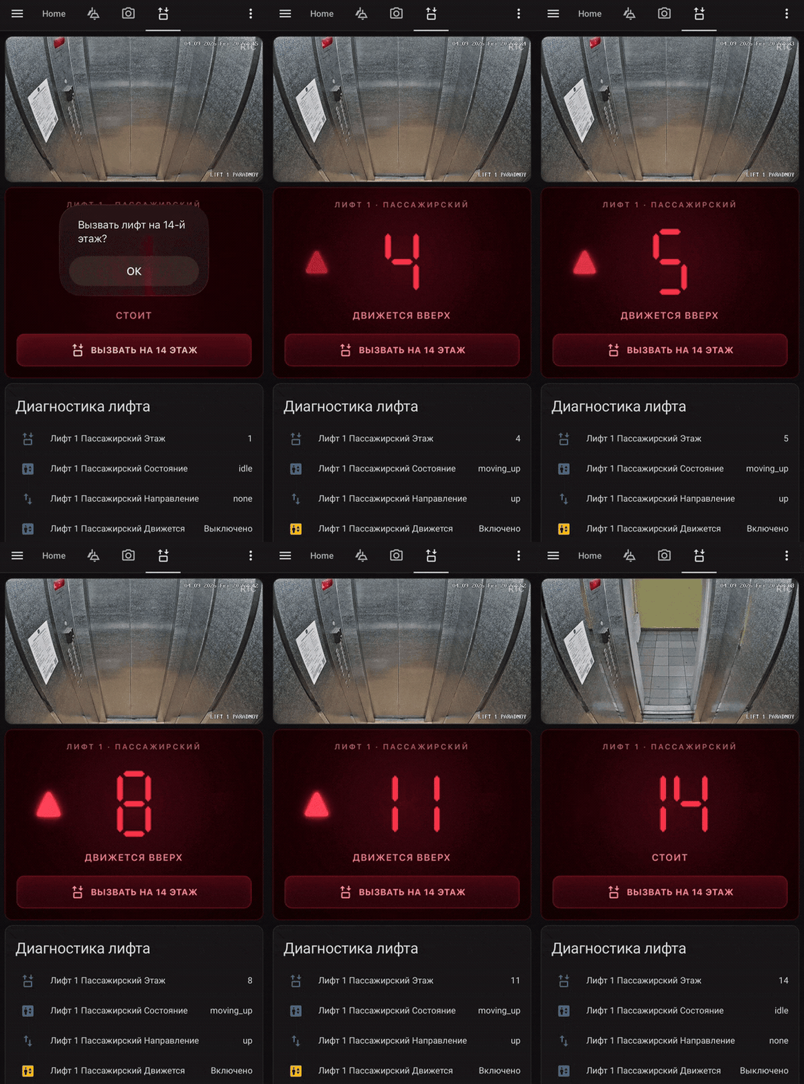
This is the complete local loop in action: the camera feed stays inside the building network, recognizer v6 reads the seven-segment indicator, and Home Assistant updates the confirmed floor, direction, movement state, and confidence in real time.
Testing it like the real world
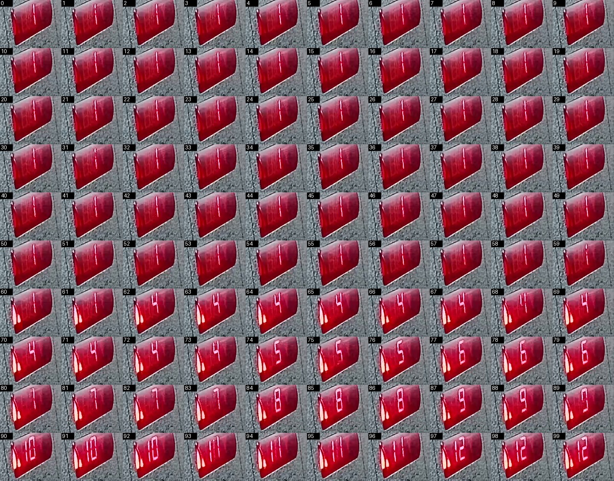
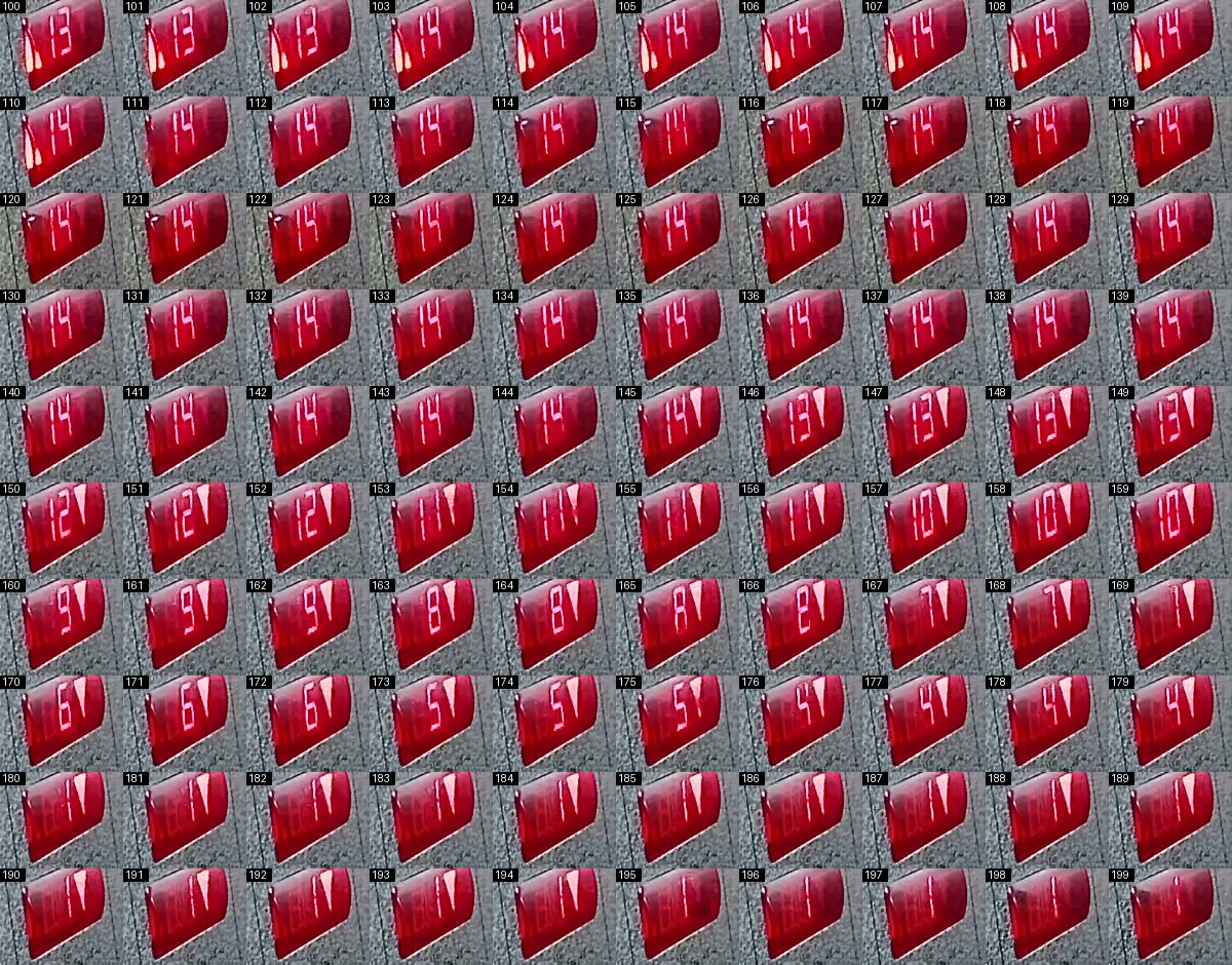
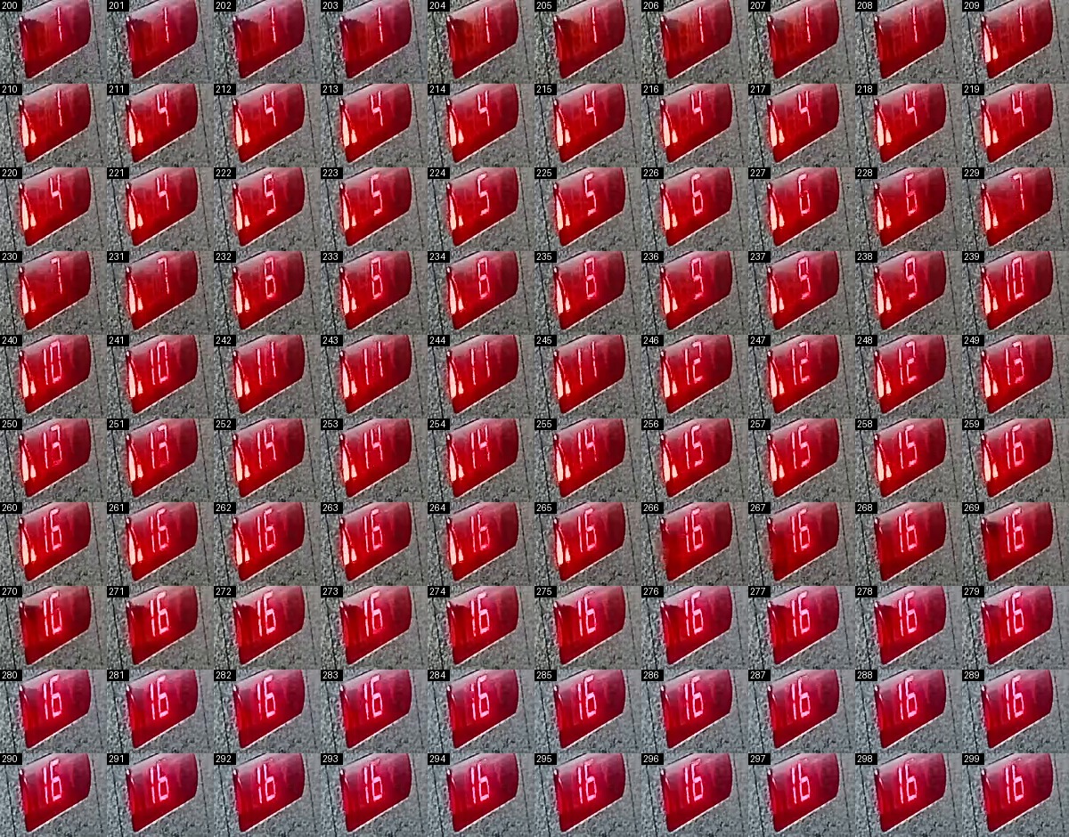
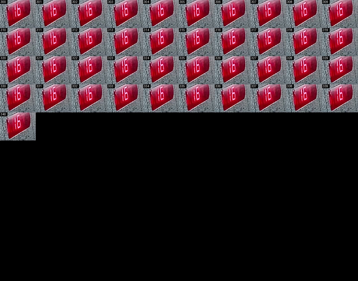
We recorded and replayed complete rides rather than testing only hand-picked
still images. The main calibration journey covered 14 → 1 → 16 → 14; another
earlier validation sequence covered 1 → 14 → 1 → 16. Contact sheets show the
flicker, exposure changes, reflections, and imperfect frames that the algorithm
must survive between the obvious digits.
| Validation ride, part 1 | Validation ride, part 2 |
|---|---|
 |
 |
| Validation ride, part 3 | Validation ride, part 4 |
|---|---|
 |
 |
New versions first ran as shadow services with separate MQTT topics. Only after their output matched the recorded rides and live ground truth were they promoted while preserving the existing Home Assistant entity IDs.
The later field failure was especially useful: the same code that had appeared stable began confusing floors and getting stuck. A labelled-frame audit showed that the crop had shifted vertically by about 4-5 pixels. The old fixed masks decoded only 33 of 145 sampled frames correctly; compensating that shift raised the direct result to 141 of 145. Version 6 therefore aligns every frame before recognition instead of assuming the camera geometry can never move.
The v6 candidate produced 361 correct and 0 wrong accepted results on a fresh full-route replay, then 236 correct and 0 wrong on an independent holdout ride. It also passed deliberate wrong-state recovery, lost-alignment and stalled-stream tests. Those measured runs are stronger evidence than the earlier short period of apparently perfect daily operation.
This is a report from daily operation on one installation, not a claim of universal, formally measured 100% accuracy on every elevator and camera. The repository includes replay material and deterministic code so the result can be inspected and reproduced instead of taken on faith.
The recognizer source and its calibrated models are in recognizer/.
Installation-specific camera, network, and MQTT credentials are deliberately
excluded.
Project status
The system is working and used daily. Public, redacted source is included for the relay, display and recognizer, together with example Home Assistant automation, architecture notes and recovery guidance. Version 6 adds camera registration and reproducible reliability tests.
Author
Created by Yehor Arseniev, a Kyiv-based entrepreneur and hobbyist building his first electronics and software project in public.
Safety boundary
Call14 does not control elevator movement, doors, brakes, or safety systems. The relay only reproduces a normal press of the existing hall-call button, and the camera side only observes the existing cabin indicator.
This hobby project is not a life-safety or evacuation system. Building rules, official emergency guidance, and restrictions on elevator use during fires, power failures, or other emergencies always take priority.
Coming next
- One-command recognizer installation helper
- Repeatable offline replay tests and a small privacy-safe sample dataset
- Final wiring diagrams
- Release packaging and checksums
Comments